Ready for calibration
Calibration RV5 – Symetrical Clipping
##Note: Things to watch out for to ensure a trouble free calibration
- Make sure to connect the signal generator to the EQN solidly
- Use a preamp to get a signal high enough into the EQN
From my understanding of this process is that, you are trying to get a sine wave to distort inside the EQN. You are not to feed it a distorted sine wave but a sine wave that becomes distorted inside the EQN because it is being fed the signal too hot into the EQN.
The EQN requires a high sine wave signal in order for the sine wave to clip on the Oscilloscope in the RV5 callibration process.
This took me a while to get but I think what I have done is correct. 🙂
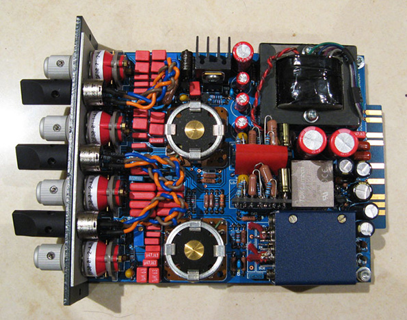
I installed my EQN on it’s own in my lunchbox on the far left, so that I can have access to the RV4 and RV5 trimpots
I used my Macbook Pro as the signal generator, using Logic software that can produce a 1Khz sine wave
I connected the Macbook Pro out to a Great River preamp to boost the signal
I connected the Great River preamp out to the input of the EQN through the lunchbox
I connected the probe of my Oscilloscope to Pin 2 of the EQN output through the lunchbox
I connected the ground cable of my probe to Pin 1 of the EQN output through the lunchbox
I set my EQN as follows: EQ in, ALL frequencies set to OFF, Gain knob to 0
I turned the RV4 Counterclockwise to as far as it can go, so that the output stage is fed the incoming signal in the EQN as high as possible to help cause the sine wave to clip on the Oscilloscope
In Logic, I set the sine wave level to Max(in the red)
The GR input leds shows red
I turned the output knob of the GR so that the output led of the GR is red
I ended up with this reading on my Oscilloscope, where the clipping is on the bottom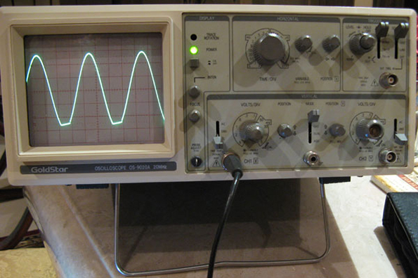
The problem with this, is that if I turn RV5, to try to get both clipping top and bottom, it actually makes the bottom clipping wider than the top. I have realised in order to get a symetrical clipping, I have to get my initial clipping to start at the top, and not the bottom. I have noticed that the bottom clipping increases at a larger rate than the top clipping hence, the funny shape sine I got.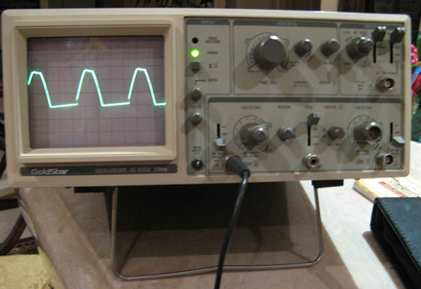
In this situation, since the clipping was at the bottom. I turned RV5 counterclockwise, which slowly rounded the bottom clipping into a smooth sine again.
I decided to boost the signal by pressing the impedence button on my GR and then boosted the GR output knob more until this time, I got a top clipping.
I turned RV5 clockwise until the bottom of the sine wave started to clip and I stopped turning RV5 until I got a similar size bottom clipping to the top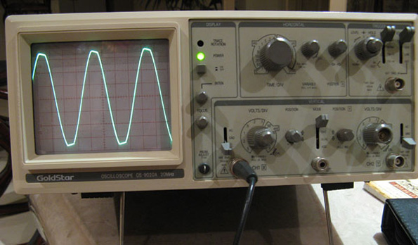
I tested my EQN after using this method of calibration and so far so good. The unit sounds pretty good!!!
Calibration RV4 – Gain Matching EQ in/bypass
Quote author=dmp link=topic=37604.msg564881#msg564881 date=1311515759
This is my understanding:
RV4 sets the level of the EQ. It’s purpose is to match the signal level to unity.
So run a signal through the EQ in bypass and observe the level, then engage the EQ and match the level using the trimpot.
- I inserted the EQN into my DAW system
- With EQ off, I fed the EQN a sine wave and observed the levels showing on my DAW
- I reseted all my EQN settings so that it is zero
- I turned the EQ on and compared the levels showing on my DAW. If it’s higher or lower, I adjusted RV4 till it matched the levels shown when EQ was Off. My levels were O.K. so I did not have to adjust RV4
“The James Fix”
………………………………………………………………..
Apparently there is an issue with this build as outlined by jrowell:
………………………………………………………………..
The symptom is LF response shelved below about 500 Hz, -1.8dB down, or so, with EQ in and all bands set to off.
If you are doing just mid or top EQ, this is a problem.
If the LF band is set to off, the response droops below 500Hz.
Since I am a vintage N*v-e service technician, I knew the issue would be in the off paths of the LF freq switch.
The offs go to one side of C29, a 10nF. The other end of C29 feeds the BA205 cap buss.
The pot wiper goes to one end of R10, a 12K. The other end of the 12K goes to C30 and to the LO/HI amp input.
The pot wiper is normally permanently connected to the off positions. It is not here.
The offs end of C29 and the wiper end of R10 are also normally connected together. Again, not here. This is pin L on an original BA205 board diagram.
Basically we have two pin L points. They need to be connected.
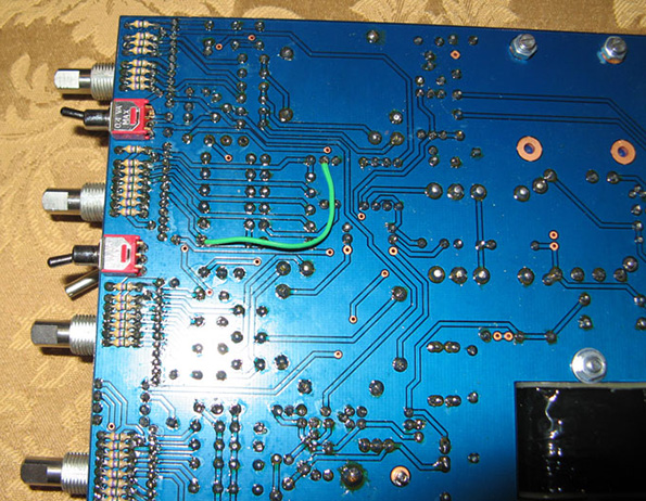
All this can be resolved by connecting the offs end of C29, (side nearest the switch) and the wiper end of R10, (the end closest to the inductor) together with a jumper wire.
Boom, no droop in LF with EQ in and LF set to off.
LF EQ at full cut or boost stays basically identical. Curve is maybe a tad more relaxed.
They actually are a bit flatter than an original, with this corrected.
\\\\\\\\\\\\\\\\\\\\\\\\\\\\\\\\\\\\\\\\\\\\\\\\\\\\\\\\\\\\\\\\\\\\\\\\\\\\\\\\\
I decided to implement this fix:
It wasn’t that hard to do, but it was just a pain to go out of my way and pull things apart and put back together again. Have not tested yet whether the fix improved anything but will do so in the future.


Feedback
*To embed code in Feedback, insert code between "pre" tags.