Quick notes
R29 is a resistor between 600r to 1.2kohm. In Petes BOM “TDB” means “To be determined”. Its not a part ::)
1 builder used 1K for R29 but was getting 1db gain loss when they’re inline, both while engaged and bypassed so Pete recommended 750r for R29.
RV4 & RV5 are little blue trimmers.
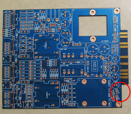
If you are not getting enough gain from your unit with RV4 adjusted, then you must lower the value of R29 to increase the gain in the output amp.
“I can help you out on the trimmer adjustment, the rv4 is the gain trimmer, it is in-between the EQ section and the output amp. RV5 is to adjust the output stage, so that the distortion is symmetrical, you need a scoop to adjust this properly, check the ez1290 build from Madriaanse, in his build pdf is a explanation how to :-)”
– DJN
RV4 & RV5 – the alignment procedure for these trimmers is similar to the ‘symmectrical clipping’ process on the 1290 preamp. (I think you need an oscillator to do this??)
…………………..
Corrected on BOM Exel – Petes BOM 1MH meant to be 1mH
66 – on BOM Exel RF Inductors 1000uH (1mH) 130mA 14ohms
RF Inductors 1000uH 130mA 14ohms = http://au.mouser.com/ProductDetail/EPCOS/B78108S1105J/?qs=v4Mlc8l4PHm9xnPqu6pYww%3d%3d
(referred to as choke)
…………………..
Grayhill switch pin:
If you loose the pin for your Grayhill switch, use the leg of a resistor and cut to size.
…………………..
The replacement screws for the input transformer are a little too long and need to be shortened which sometimes damages the threading.
…………………..
71 – 1N400X series, 1N4001 will do
Rectifiers Vr/50V Io/1A T/R
http://au.mouser.com/ProductDetail/Fairchild-Semiconductor/1N4001/?qs=sGAEpiMZZMutXGli8Ay4kJFypYesfd9y2GUYLufLOL0%3d
…………………..
80 – DC-1 TDK LAMBDA CC6-2412DF-E
CONV DC/DC 6W DUAL 24V +-12V PCB
http://parts.digikey.com/1/parts/733027-conv-dc-dc-6w-dual-24v-12v-pcb-cc6-2412df-e.html
…………………..
27 – 4M7 miniature
Carbon Film Resistors – Through Hole 4.7M OHM 5% 1/4W
Dimensions: 1.7 mm Dia. x 3.2 mm L
http://au.mouser.com/ProductDetail/KOA-Speer/CFS1-4CT52R475J/?qs=sGAEpiMZZMu61qfTUdNhG1dhquwH4o0F6GnhHghqdcU%3d
…………………..
RV1, RV2, RV3 linear small format pots should be the PRV6/PARV6 kind of size with center detent
…………………..
I have finally got around to ordering the parts from Mouser and Digikey. I am very excited! ;D
I have placed a word version of the parts I ordered on the first post of this thread if anyone wants to download it for guidance. The hyperlinks on the word document are active so you can see what I have ordered except for the Digikey list section which you will have to cut and paste into the Digikey website.
Please inform me if you notice something wrong with it so that I may be able to correct it.
Hopefully someone will find this list useful. Thanks to the other posters who placed their list or parts up which has helped me to verify some of the components I have chosen. I went for lower tolerances on most of my components like 1% than 5% for the resistors and chose mid price components than the cheapest.
I am actually glad that it took me this long, because the first time I was gathering my BOM list, some were not available, now all the parts are available for a hopefully smooth journey : ))
Regarding the knobs I used for my build, I was very much impressed by Mako’s EQN reasoning behind his knob selection – webpage http://mnats.net/pp-eqn_notes.html (recommended reading because he identifies some alternative build process and provides useful build instructions). His recommendation of parts was also taken into consideration when I built my list and I have actually used some of his selection and also Kato, so thanks guys.
So if you refer to both my Word ordered parts list and the Excel BOM list, you should have a list of all the components I used in this build which I hope is complete and correct. Only time will tell…
Sawed off the 51x tab since my main use for this build would be for the API lunchbox (16 volts).
I first considered making this swappable with the 51x rack by keeping the 51x tab on but I had already spent money on the DC-DC converters and parts and did not plan to go 51x, so I decided it wouldn’t be worth it for my purpose.

Be careful if you decide to saw this tab off. Be sure to have the board secured well because I felt that with the swinging motion and sometimes the saw gets jammed that there may be a possibility that you snap the board while sawing it.
opAmps
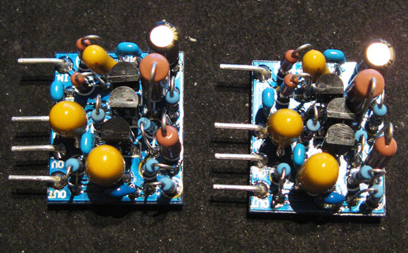
Took me almost 2 days to do these little opAmps. I may have to trim the pins length, I will find out I guess once I solder the sockets on the main PCB.
I used BC184C transistors that had a HFE of over 600.
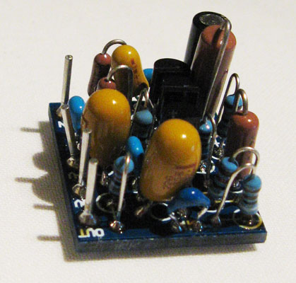
I made sure that all components did not touch each other at all even though they were so close together. You may have to do some component angling to ensure space between components.
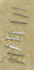
I used the pins supplied in Pete’s kit for the pins for the opAmps so that it can be connected to the PCB board.
I soldered all the other parts first before soldering the pins. I slightly bent the pin before soldering the pin for those tight areas. Then I bent the pin into shape after.
I was very careful when bending the pins after soldering because it is close to the edge of the board and may weaken the board or snap it.
I think the key is to firmly hold the little board and bend the pins very slowly with a long nose pliers.


Feedback
*To embed code in Feedback, insert code between "pre" tags.